How to draw the antenna on the PCB board
When designing a printed circuit board (PCB), there may be a need to include an antenna for wireless communication. In this article, we'll cover the steps for drawing an antenna on a PCB board.
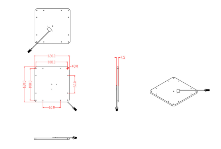
1. Determine the Frequency Range
Before drawing an antenna on a PCB board, it's important to determine the frequency range that the antenna will operate at. This will affect the size and shape of the antenna. For example, if the antenna is operating at higher frequencies, it will be smaller in size compared to an antenna operating at lower frequencies.
2. Choose the Antenna Type
There are many different types of antennas that can be used on a PCB board. Some common types include monopole, dipole, and patch antennas. The choice of antenna will depend on various factors, such as frequency range, available board space, and antenna efficiency.
3. Determine the Antenna Dimensions
Once the frequency range and antenna type have been selected, it's time to determine the antenna dimensions. This includes the length, width, and height of the antenna. The dimensions will depend on the desired resonant frequency, which is the frequency at which the antenna will operate most efficiently. The size and shape of the antenna can be optimized through simulation tools like HFSS or CST.
4. Place the Antenna on the PCB Board
The placement of the antenna on the PCB board is crucial for the overall antenna performance. The antenna should be placed at a location that minimizes interference, while also providing optimal radiation patterns. It's important to keep the antenna away from other components that could have an impact on its operation.
5. Create Ground Planes
Ground planes are necessary for most antenna designs to ensure proper functioning. For instance, monopole antennas require a ground plane or field to operate as the signal is radiated into free space. Ground planes are usually made from copper, and the layout is often dependent on the type of antenna and its dimensions. The ground plane should be connected to the antenna through a feedpoint.
6. Route the Feedline
The feedline is the connection between the antenna and the transmitter or receiver. It's essential to route the feedline carefully, as it can affect the performance of the antenna. The feedline can be a coaxial cable, microstrip, or a coplanar waveguide, depending on the antenna type and the frequency.
7. Check the Signal Integrity
Before sending the PCB board for manufacturing, it's good practice to check the signal integrity of the antenna. This can be done using simulation software like ADS or AWR. It will help to check the antennas' impedance, radiation patterns, and bandwidth.
Conclusion
Designing an antenna for a PCB board requires a good understanding of the antenna specifications and the PCB layout. The antenna's performance can be improved by optimizing its size and shape, placing it at a suitable location, and grounding it correctly. With these steps in mind, you can design an efficient and reliable antenna for your PCB board.
